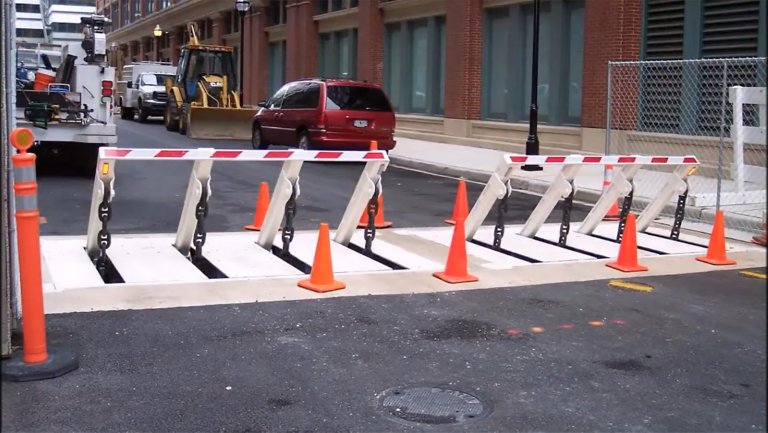
In the following discussion, reference is made to a surface of a foundation to which the wedge-style barrier is mounted. In the detailed personifications, the top side of the support is substantially flush with the surface area of the structure. In such personifications, the wedge-style barrier may be mounted directly to the surface of the structure. Nonetheless, in other embodiments, the upper side of the support might be somewhat increased over the surface of the foundation or somewhat recessed below the surface of the structure. 1 is a front perspective view of an embodiment of a surface-mounted wedge-style barrier 10. As revealed, the barrier 10 is mounted to a surface area 12 of a structure 14(e. g., a superficial structure ). The foundation
Wedge Barriers
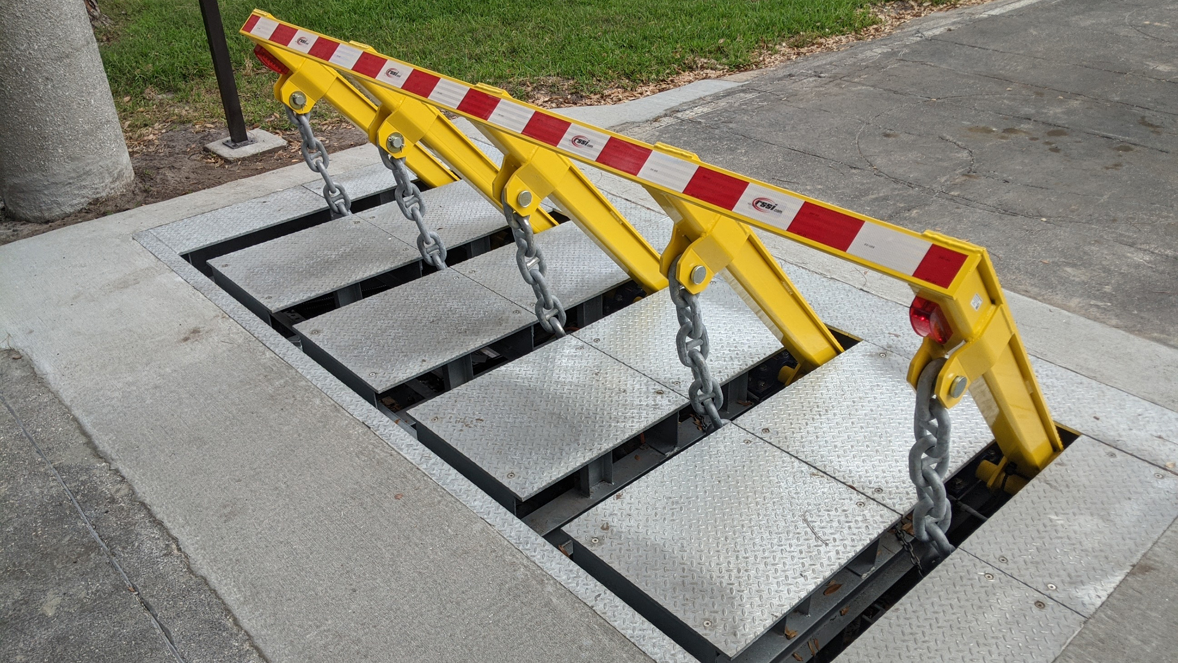
14 and the surface 12 to which the barrier 10 is secured may protected made from concrete. 2, the barrier 10 is installed to or consists of an anchor or subframe (e. g., support 30 displayed in FIG. 2 )safeguarded beneath the surface 12. The bather 10 might be bolted to the support or protected to the support by other mechanical fasteners. In the detailed personification, the barrier 10 consists of a wedge plate 16, which includes a part that is substantially identical with the surface 12 when the barrier 10 remains in the withdrawed setting. To put it simply, lorries or people might overlook the obstacle 10 when the obstacle 10 is in the pulled back setting and experience mild altitude about the surface area 12 while on the obstacle 10. As gone over in detail listed below, when the barrier 10 is in the released placement, the wedge plate 16 is held and sustained in a raised setting by a training mechanism of the obstacle 10. In addition, the components 18 may be bolted or otherwise mechanically paired to each other. In this way, repair or replacement of several parts 18 might be streamlined and streamlined. That is, repair service or substitute of single elements
18 might be done quicker, conveniently, and cost efficiently. FIG. In particular embodiments, the anchor 30 may be a steel website link structure consisting of plates, beams(e. g., I-beams ), and/or other frameworks hop over to here that are safeguarded within the structure 14, which might be concrete. At the surface 12, an upper side 28 of the anchor 30 may be at least partially exposed
, thus making it possible for the attachment of the obstacle 10 to the support 30. g., threaded openings)in several light beams or plates of the support 30 may be revealed to the surface area 12. In this fashion, screws 32 or various other mechanical bolts may be utilized to safeguard the obstacle 10 to the anchor 30. As the obstacle 10 is installed to the surface area 12 of the structure 14, collection of debris and other material underneath the obstacle may be reduced, and parts of the bather 10 may not be revealed to listed below grade settings. As indicated by referral numeral 52, the training system 50 consists of elements got rid of underneath the wedge plate 16. As an example, the elements 52 below the wedge plate 16 may consist of an electromechanical actuator, a webcam, several webcam surfaces, etc. Additionally, the training mechanism 50 consists of a spring setting up 54
The spring pole 58 is combined to a webcam(e. g., cam 80 received FIG. 4) of the lifting system 50. The springtimes 60 disposed about the springtime pole 58 are kept in compression by springtime sustains 62, including a dealt with springtime support 64. That is, the set springtime assistance 64 is dealt with about the structure 14 et cetera of the bather 10.
The smart Trick of Wedge Barriers That Nobody is Talking About
g., springtime support 65 )might be dealt with to completion of the spring rod 58 to enable compression of the springtimes learn this here now 60. As the springtimes 60 are pressed in between the springtime supports 62, the springtime setting up 54 creates a force acting on the cam combined to the springtime rod 58 in an instructions 66. The remaining force applied to
the cam webcam deploy release wedge plate 16 may might provided by an electromechanical actuator 84 or other various other. Because of this, the springtime assembly 54 and the actuator 84(e. g., electromechanical actuator)may run with each other to equate the web cam and lift the wedge plate 16.
As pointed out over, in the released placement, the wedge plate 16 offers to obstruct gain access to or travel past the barrier 10. The barrier 10(e. g., the wedge plate 16 )may obstruct pedestrians or cars from accessing a home or pathway. If a lorry is taking a trip towards the deployed wedge plate 16(e. For example, in one circumstance, the security legs 86 might be prolonged duringmaintenance of the barrier 10.